Optics & lighting
Validate aperture and depth of field with a test matrix
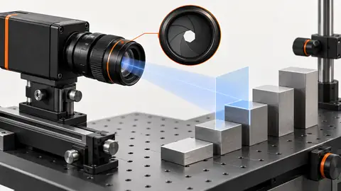
A sharp center image does not establish usable depth of field. Test the smallest relevant feature at every required height and field position.
Machine vision troubleshooting
Build repeatable contrast with the right illumination, lens and working distance.
A sharp center image does not establish usable depth of field. Test the smallest relevant feature at every required height and field position.
Separate required parts from clamps and reflections with paired lighting tests, nonoverlapping zones and explicit visibility limits.
Keep the printed symbol, its quiet zones and source coordinate mapping intact when comparing illumination or tightening a reader ROI.
Choose contrast that preserves separation, exclude tray features and define how border-touching components are handled in the count.
Choose a repeatable edge definition with controlled lighting and ROI geometry; retain raw images when threshold changes shift a measured edge.
Separate a real liquid boundary from wall reflections, seams and foam before using a fixed ROI to calculate a visible level proxy.
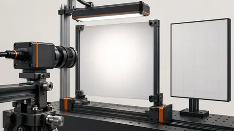
Remove stable shading only after fixing illumination and optics. A correction map cannot restore saturated pixels or changing shadows.
Choose light color from measurable defect/background separation, not the brightest image. Color changes can invert contrast and move best focus.
Preserve the whole text field through lighting comparison and ROI mapping so that a cropped or reflected character cannot silently disappear from verification.
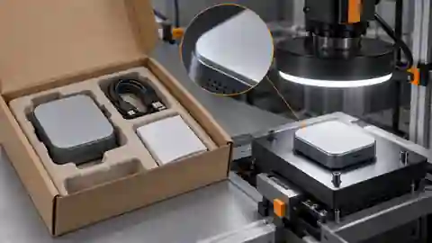
Use matched present, absent and covered-item controls to separate actual visible contents from tray edges, reflections and wrapping.
Stabilize the visible target center with controlled lighting and explicit ROI coordinates; test centroid bias from glare, shadows and clipping.
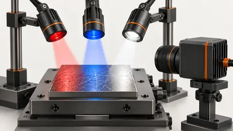
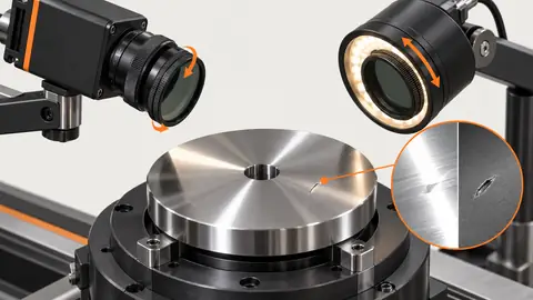
Suppressing a bright reflection is useful only if the defect remains visible. Compare unpolarized and cross-polarized images on the same scratched and good surfaces.
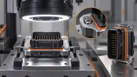
Compare illumination and inspection regions for a missing-feature check; preserve absent and obscured controls when choosing contrast.
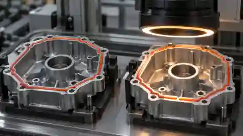
Compare light and source-linked path regions without letting reflections or an ROI crop erase a real visible gap in the seal or adhesive bead.
Compare product color on a stable object region while keeping shadows, specular highlights and colored background from silently redefining the sample.
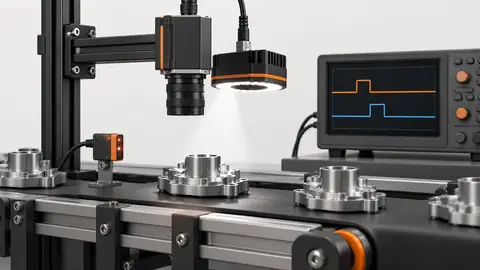
Electrical lamp trigger timing does not prove when light reaches the part. Measure the optical pulse and the supported camera exposure/flash window together.
Compare lighting directions on the same scratch and preserve the datum-to-surface region instead of hiding troublesome reflections with an arbitrary crop.
No tutorial titles match this search.
Engineering review
Send sample images, your current setup and the check that failed. Include field of view, working distance, line speed and acceptance criteria for a practical review.
Send samples for engineering review