Purpose and operating boundary
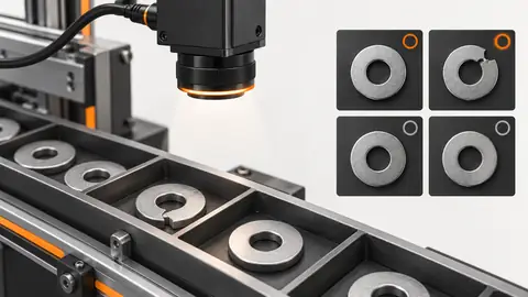
Compare lighting directions on the same scratch and preserve the datum-to-surface region instead of hiding troublesome reflections with an arbitrary crop.
This tutorial defines an engineering evaluation, not a ready-to-run product certification. The current Deyi Vision public PC example covers an EAN-13 workflow on confirmed sample images. Native OCR and detection work in the engineering code must be checked against the installed runtime, bound models and job before use. A browser template does not prove browser execution: the planned OpenCV.js backend needs separate verification. Cloud recognition requires explicit approval of the image scope, provider, model and cost. A review archive is not an executable release package. Camera, firmware and driver compatibility require their own check. All worksheet values below are hypothetical; they are not Deyi Vision measurements or customer results.
Prepare the evidence
Use a scratch with known direction and a good textured surface. Mark the light positions and keep exposure fixed throughout the optical comparison. Repeat the selected condition after restoring the fixture, not merely while leaving everything untouched. This reveals whether the recipe can be reproduced during changeover. Record ambient-light state and the time since illumination was enabled when these affect the image. Do not compare measurements taken from different masks or different bit-depth conversions as though only lighting changed. Keep the rejected optical condition in the record, including its image and the reason for rejection. A visually attractive image is not automatically the best inspection image: the selected condition must preserve the relevant feature and its separation from acceptable variation over the full agreed sample range. A surface-defect station must distinguish a material defect from a change in viewing conditions. Scratches, dents, oil, texture and a reflection can produce similar intensity changes, yet require different dispositions. Prepare acceptable parts from the expected finish range and defect samples with recorded locations and orientations. Choose a datum that remains visible when the surface changes. A reference image is useful only after its pose and illumination are comparable with the current part. An image difference is not a physical depth measurement, and a detected region does not by itself identify a defect mechanism. Decide whether dirt is a reject, a cleaning request or an excluded condition before collecting answers. Store original views of ambiguous samples rather than inventing a clean reference or a corrected label. Build a controlled optical comparison before moving the threshold. Mark the fixture, working distance, light angle and focus so that each condition can be restored. Change only the selected lighting or region variable while holding the camera settings and sample identity fixed. Retain the entire source frame beside every crop or mask, with the transform back to source coordinates. Capture both acceptable variation and a known problematic sample, including the edge of the allowed placement range. Inspect the region overlay on the original image before interpreting a numeric result. A smaller region can hide a failure rather than improve inspection, so excluded areas need an explicit engineering reason.
Procedure
- Capture grazing light from opposing directions so that a scratch parallel to one direction is not the only sample.
- Compare a diffuse condition with the directional condition; retain glare and saturation counts beside the defect contrast.
- Locate the part from its datum, then transform the inspection region to the original frame before excluding edges.
- Restore the fixture and repeat both conditions on finish variants; save the condition that loses the scratch.
Interpret the trial
The hypothetical contrast improves from 0.0286 to 0.2174 when the light direction changes. This shows contrast for this sample, not a universal best light. A region that avoids the glare by deleting the actual defect is invalid.
Recording worksheet
| Record | Value / observation | Interpretation |
|---|---|---|
| Condition A | B = 180; D = 170 | Contrast = 0.0286 |
| Condition B | B = 140; D = 90 | Contrast = 0.2174 |
C = abs(B - D) / (B + D)
C_A = 10 / 350 = 0.0286
C_B = 50 / 230 = 0.2174
Two engineering views
Two engineering views · 1
The diagram shows the order of checks. Each arrow requires recorded evidence; it does not imply an implemented automatic connection. Source frame → Light condition → ROI → Contrast.
- Source frame
- Light condition
- ROI
- Contrast
Two engineering views · 2
The diagram shows the order of checks. Each arrow requires recorded evidence; it does not imply an implemented automatic connection. Baseline → Candidate → Same sample → Decision.
- Baseline
- Candidate
- Same sample
- Decision
Failure diagnosis
- If rotating the part reverses the decision, inspect light-to-scratch orientation before retraining.
- If the defect touches the ROI edge, check registration and padding rather than trimming it away.
Acceptance and handover
Select a reproducible condition that separates relevant scratches from permitted texture across the agreed orientations. Record excluded regions with their engineering reason.
Keep the source images, the expected decision, the exact revision and the complete result record together. Freeze the evaluation set before selecting the final parameters. If those answers are later used to tune the workflow, mark that set as development data and obtain a new independent acceptance set. Keep Review, NoResult, execution error and missing acquisition visible in the denominator; do not turn them into passes by filtering rows. Save a reproducible failure alongside the successful sample. The handover should identify who may change the recipe, how a prior approved revision is restored and which device output remains inhibited until acceptance. A software result alone does not establish that a moving physical part reached the correct destination.
Sources and technical references
These references explain the methods and limits used in this tutorial. Example checks are guidance; production acceptance requires evidence from your own samples.
- Deyi Vision machine vision software: evaluation scopeDeyi Vision
Public EAN-13 PC evaluation scope and separate hardware/production acceptance.
Checked - Reflective Metal Scratch Inspection Lighting RouteDeyi Vision
Compare grazing/diffuse lighting with finish and orientation variation; 2D appearance is distinct from depth measurement.
Checked - Geometric Image TransformationsOpenCV
Source/destination coordinate mappings, affine/perspective transformations and interpolation; image geometry does not certify an installed Deyi executor.
Checked
Component and selection references
- Machine Vision Lighting
- Reflective Metal Scratch Inspection Lighting Route
- Automated Visual Inspection
- How to Choose Machine Vision Lighting
- Machine Vision Lighting Types
- Machine Vision Lighting Basics
- Backlight vs Coaxial Lighting
- Automotive Metal Surface Defect Inspection
- Metal and Surface Inspection
- OPT Lighting Alternative
- EAN-13 traceability: lighting and quiet zones
- Lighting and ROI for a visible liquid boundary
- Calibrate flat-field shading without hiding bad data
- Compare red, blue and white illumination by defect contrast
- OCR labels: light and field geometry
- Choose lighting and ROI for open-package contents
- Run a polarization A/B test for glare
- Seal and bead appearance: lighting and ROI
- SKU color sorting: light and object mask
- Verify the optical strobe inside the exposure window
- Surface defects: acceptance and line output
- Surface defects: bounded AI evaluation
- Surface defects: camera sampling and motion
- Surface defects: false-alarm diagnosis