
When to review telecentric lenses.
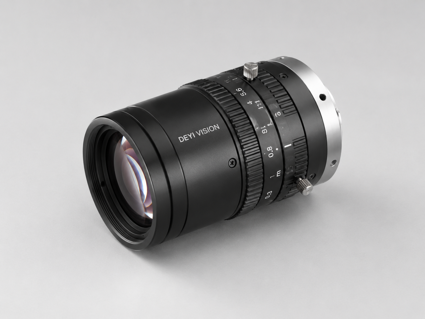
The Telecentric Lenses route fits dimensional inspection, edge measurement, low-distortion calibration projects. Use telecentric optics when perspective error changes the result.
Product route
Telecentric optical routes for precision measurement, low-distortion edge capture and repeatable gauge-style inspection.

The Telecentric Lenses route fits dimensional inspection, edge measurement, low-distortion calibration projects. Use telecentric optics when perspective error changes the result.
Low distortion, Measurement optics, Stable edge capture are only the starting point. Also confirm field of view, working distance, line speed, interface, trigger timing and mounting limits.
Share sample images, good and bad parts, current reference model, target defect, tolerance, production speed and available fixture space.
When this route is a good fit
Swipe horizontally to compare buyer situation, inspection constraint, recommended route and what to send.
| Buyer situation | Inspection constraint | Recommended route | What to send |
|---|---|---|---|
| Measurement lens review for low-perspective-error inspection | Telecentric measurement RFQ | Measurement lens route for low-perspective-error inspection. | Send object size, sensor size, WD, tolerance and edge definition needs. |
| Object-side and image-side telecentric review for stricter measurement stability | Bi-telecentric route review | Object-side and image-side telecentric route for stricter measurement stability. | Confirm magnification, sensor format, tolerance and calibration method. |
| Object-space telecentric review when part height variation changes apparent size | Object-space telecentric review | Object-space telecentric route when part height variation changes apparent size. | Provide part thickness range, depth variation and measurement feature. |
| Engineering review matched to measurement tolerance and field size | Measurement optics supplier review | Engineering route matched to measurement tolerance and field size. | Send drawing, tolerance table, FOV, WD and camera model reference. |
How buyers should compare this route
Telecentric Lenses should be evaluated when the project is tied to dimensional inspection, edge measurement, low-distortion calibration. A useful review starts from the part behavior, target feature, motion condition and current failure mode, then maps those limits to the right component family instead of forcing one catalog model.
Use telecentric lenses selection as a system decision: lens, lighting, fixture, trigger, interface and software all affect repeatability. The safest shortlist is created only after sample images, line speed and output constraints are reviewed together.
What engineering should confirm first
This workflow keeps the RFQ focused on the real inspection constraint and reduces the risk of buying a component that works on paper but fails under production lighting, motion or fixture variation.
Reviewed selection basis
Related solution routes
Build automated visual inspection systems for defect detection, presence checks, surface inspection, orientation, measurement and repeatable pass/fail output.
SolutionPlan a complete vision inspection system for defect checks, presence, measurement, barcode reading and pass/fail output.
Application case briefs
Application brief for checking connector pin presence, orientation and bent-pin risk with camera, lens and controlled lighting.
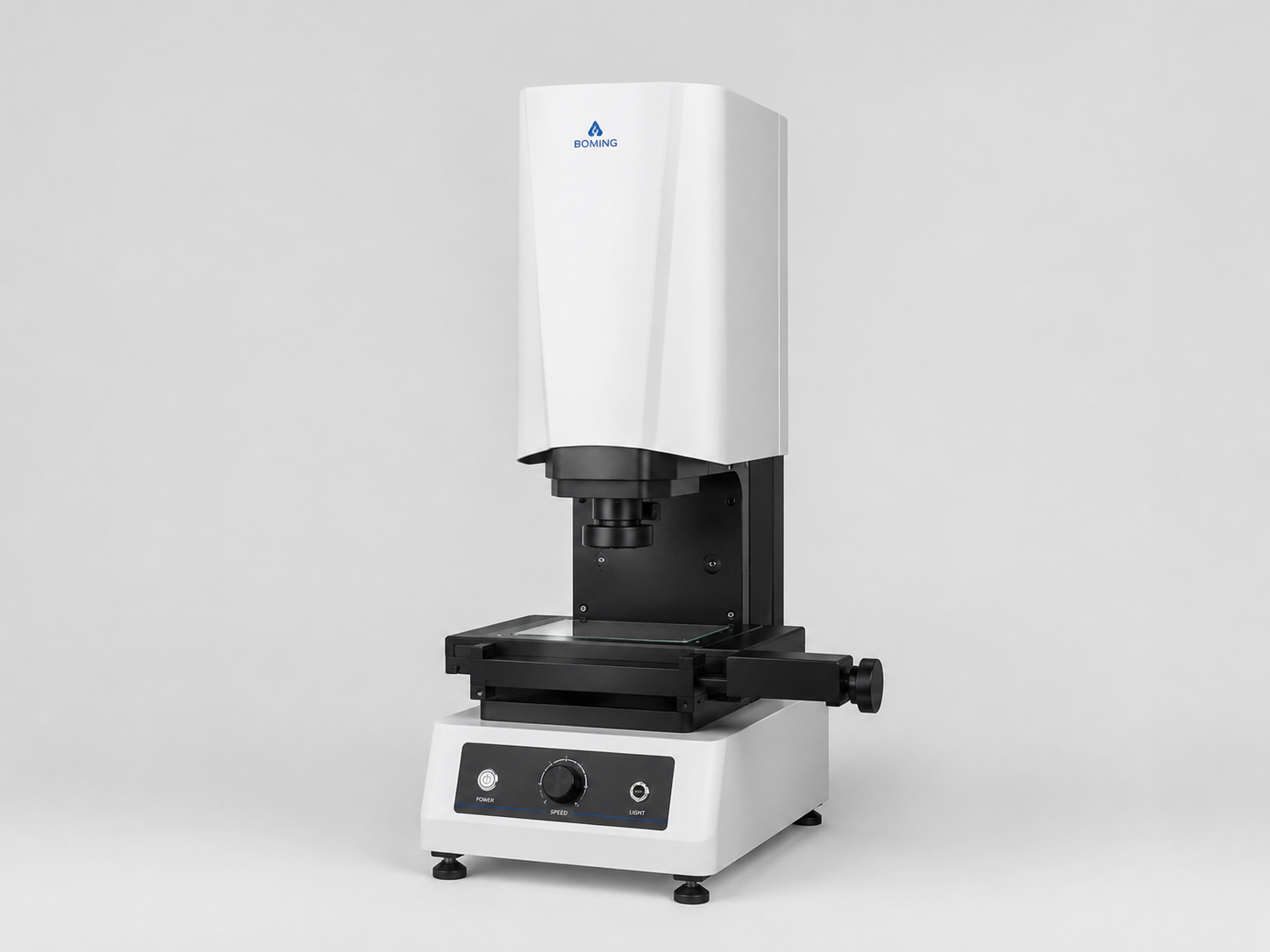
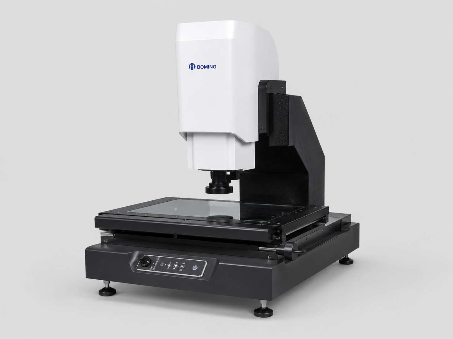
Dimension measurementApplication route for fast dimensional checks on stamped, machined or molded parts using instant measuring systems.
Automotive parts inspectionApplication route for scratches, burrs, dents and reflective metal surface checks using lighting-first machine vision selection.
Related buying guides
Decide when telecentric optics are justified by measurement tolerance, part height variation and fixture repeatability.
ResourceLearn what telecentric lenses do, when they improve measurement repeatability and when regular machine vision lenses are enough.
ResourceCompare telecentric and regular machine vision lenses by perspective error, measurement tolerance, working distance, field of view and budget tradeoff.
ResourceSelect machine vision lenses by field of view, sensor size, working distance, aperture, distortion, resolution and whether the task needs telecentric measurement stability.
Reference alternatives
Review Baumer-style vision camera requirements before selecting resolution, interface, lens and lighting route.
CompareA neutral selection guide for teams comparing Keyence-style integrated vision systems with component-level inspection routes.
ComparePlan a 3D vision route for height, profile, weld, gap and geometry inspection before choosing a sensor family.
CompareReview Hikrobot-style camera, lens, lighting and barcode requirements against a factory-direct component route.
Product RFQ
Send working distance, target size, speed, defect type, competitor model or sample images before locking a part number.
Request engineering RFQProduct FAQ
Start with the inspection goal, field of view, working distance, line speed and target tolerance. Then match telecentric lenses with lens, lighting, mounting and I/O requirements instead of choosing by part number alone.
Send good and bad sample images, target feature size, field of view, working distance, speed, trigger method, interface requirement and any current reference model. That lets engineering confirm whether telecentric lens is the right route or whether another product family is safer.
Avoid catalog-only selection when the part is reflective, moving quickly, tolerance-sensitive, space-limited or already failing under manual inspection. In those cases, lighting, lens, fixture and software behavior often matter as much as the component specification.
Send part photos or drawings, target defect or measurement goal, field of view, working distance, line speed, accuracy target, lighting limits and any current camera, lens, light, barcode reader or competitor model.
Use 2D when contrast, edges, labels or position are enough to judge the part. Use 3D when height, profile, gap, volume, weld shape or surface geometry decides pass or fail.
Start from the defect and material surface instead of the camera model. Backlight helps edge measurement, coaxial and dome lighting help reflective surfaces, and bar or ring lighting often works for general presence and defect checks.