What the test resolves
A sharp center image does not establish usable depth of field. Test the smallest relevant feature at every required height and field position.
This is a vendor-neutral commissioning method. Check the exact camera, lens, sensor or controller manual before changing settings. The numerical worksheet is hypothetical, not a Deyi Vision measurement or a product specification.
Describe the inspection feature before judging sharpness. A broad outline may remain recognizable while a narrow scratch or close pair of edges merges into the background. Specify which feature must be resolved, where it may appear and what decision depends on it. This test establishes usable performance for that requirement, not an unrestricted depth-of-field rating for the lens.
Operating prerequisites
Define permitted object-height range, feature size and minimum contrast before testing. Dimensional applications also need scale stability; apparent focus does not guarantee correct size.
Measure the relevant height range from the actual fixture and parts, including seating variation. Keep the target face orientation controlled so a height test does not quietly become a tilt test. Distinguish the permitted object-height range from variation in camera mounting. These are separate causes of image change and should have separate evidence if both occur in the installation.
Bench and records
Prepare a resolution/edge target, height shims or translation stage and reference dimension. Fix working distance, wavelength and focus at nominal height; record exposure compensation.
Record the focus-ring position and aperture setting before each height sweep. Use the same target feature at each field location and identify its physical size. Verify that shims or the translation stage move the target without bending it or changing illumination. Save raw frames and settings, and use consistent display scaling when comparing edge appearance.
Run the test
- Capture the target at −2, 0 and +2 mm for f/4, f/8 and f/16, where supported.
- Repeat at center and all four corners without refocusing for each height.
- Record feature contrast, edge width and dimensional error; adjust light/exposure only within production constraints.
- Run actual parts through the chosen setting at height extremes and repeat after remounting.
Return to nominal height after testing the extremes to check that the fixture and target have not shifted. Do not refocus at each height: doing so measures repeated focusing rather than the depth available in the locked setup. If an aperture change is accompanied by refocusing, label that run as a distinct configuration. Preserve both the unchanged-focus evidence and the independently optimized result.
Hypothetical worksheet
Hypothetically the worst contrast across the grid is 0.18, 0.31 and 0.21 for the three apertures. With a predeclared 0.25 criterion, only f/8 passes this example. Stopping down further can lose resolution to diffraction.
contrast = (I_max - I_min) / (I_max + I_min)
required_z = [-2, 0, +2] mm
minimum_contrast_example: f/4=0.18; f/8=0.31; f/16=0.21
acceptance_example: minimum_contrast >= 0.25| Quantity | Hypothetical value | Meaning |
|---|---|---|
| Worst contrast f/4 | 0.18 | Below hypothetical 0.25 limit |
| Worst contrast f/8 | 0.31 | Passes this example |
| Worst contrast f/16 | 0.21 | Resolution loss still possible |
Read the worksheet as the worst cell in each aperture's grid. A favorable average can hide a failing corner or height extreme. Apply the declared contrast definition to the same feature, with regions that do not include unrelated surface texture. If the minimum passes but dimensional error fails, report the configuration as unsuitable for that measurement rather than combining the metrics into an optimistic score.
Test sequence
Test sequence
Cross every required height with aperture; assess the worst cell rather than the average.
- Height −2
- Nominal
- Height +2
- Aperture
The matrix diagram is a record structure, not a prediction of equal performance at every location. Attach a raw image and feature result to each cell. Mark unavailable or invalid captures explicitly instead of substituting a nearby result. Missing evidence at the least favorable position prevents a claim that the full declared height range has been checked.
Interpret the evidence
Interpret the evidence
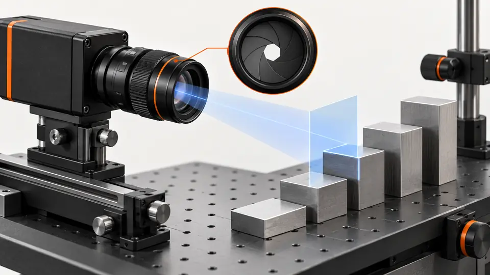
The target moves through object depth while camera focus stays fixed; corner positions are checked separately.
- Near plane
- Nominal plane
- Far plane
- Fixed focus
The geometry diagram emphasizes a fixed imaging arrangement while the object changes height. The near and far limits need not behave symmetrically, so preserve results from both sides of nominal. Compare measured reference dimensions and edge contrast separately. A visible edge may move in the image or change scale even when its appearance remains convincing; apparent clarity is not measurement accuracy.
Troubleshooting
- Good center results with weak corners suggest field curvature or lens limits.
- Good contrast with changing measured size indicates magnification/perspective error, not solved by aperture alone.
If all positions degrade together after stopping down, compare the finest target detail and available signal before increasing detector sensitivity. If only a field region fails, inspect target alignment and lens performance at that location. If images fluctuate while the target remains stationary, investigate vibration, exposure and illumination stability before interpreting the variation as a depth-of-field limit.
Acceptance and handoff
Require all height/field cells and dimensional-error limits to pass with validated exposure. Save the complete matrix, not only the best image; use a telecentric evaluation if scale changes dominate.
Archive the raw files, settings, sample identifiers and decision limits together. Discuss the documented requirements with Deyi Vision using the related product and preparation guides below.
Validate the chosen aperture with real parts containing the required feature, including the declared height limits and field positions. Repeat after the mount is removed and reinstalled, using the saved mechanical references. Record permissible focus and fixture conditions, and define when the matrix must be rerun. Keep failures alongside passing cells so the handoff shows the operating boundary rather than only the sharpest image.
Sources and technical references
These references explain the methods and limits used in this tutorial. Example checks are guidance; production acceptance requires evidence from your own samples.
- Depth of Field and Depth of FocusEdmund Optics
Depth of field depends on aperture and required feature resolution.
Checked - Gauging Depth of Field in Your Imaging SystemEdmund Optics
Depth of field should include a resolution criterion; sharpness alone does not guarantee magnification stability.
Checked
Component and selection references
- Machine Vision Lens Selection Guide
- Telecentric Lens vs Regular Lens
- Machine Vision Lenses
- Dimension Measurement
- Telecentric Lenses
- Instant Measuring Systems
- Telecentric Lens Basics
- What Is a Telecentric Lens?
- Stamped Part Instant Measurement
- Dimensional inspection: camera and plane setup
- Dimensional inspection: lighting and edge ROI
- Dimensional inspection: diagnose bias and drift
- Validate camera calibration across the full field
- Build a vision-measurement uncertainty worksheet
- Test subpixel edge repeatability separately from bias