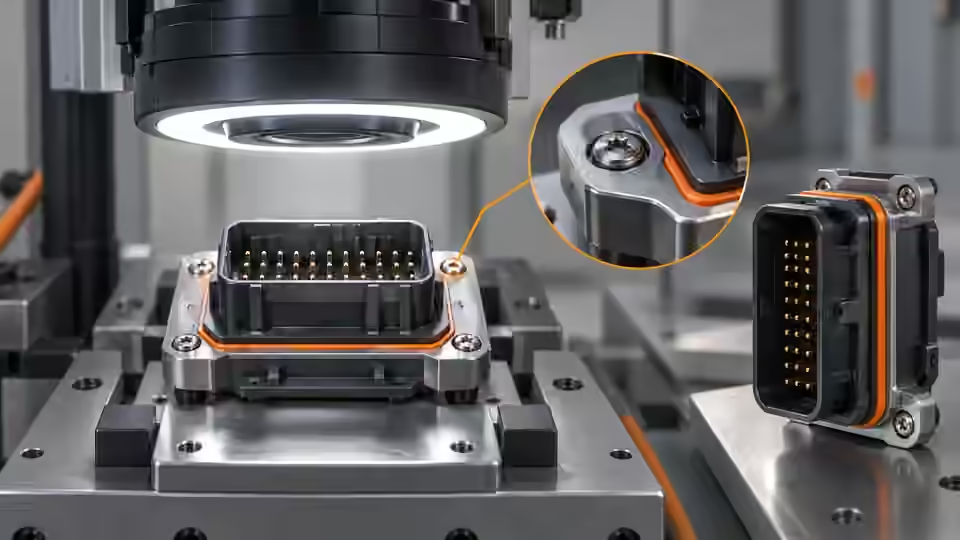
Define the part-to-background contrast
Define the visible evidence for each required component before selecting a light. Distinguish the component boundary from a bright fixture edge, printed mark or loose debris inside its expected zone. The optical contract must say which surface transition is being observed and why that transition belongs to the part in the reference specimen. A configured zone may receive a part label for bookkeeping, but that does not make every foreground blob there a recognized SKU. Keep wrong-material and empty-zone controls available so the lighting comparison tests identity limits as well as the appearance of a correctly assembled example.
Compare illumination on matched assemblies
Compare diffuse front lighting, directional lighting or an appropriate silhouette approach on the same identified assemblies with unchanged camera geometry and exposure. Change only the selected illumination variable for each pair. Retain original frames from correct, missing-part and misplaced-part references, including the unsuccessful option. A light that separates the normal part but also makes a fixture screw resemble the missing feature has not solved the task. Record where the proposed contrast improvement occurs and which observations would refute it. Select a candidate from the complete controlled comparison, rather than tuning illumination until an isolated passing preview looks convincing.
Control specular features without hiding defects
Inspect highlights on polished retaining features and shadows near clamps over the permitted pose range. If a diffuser or polarization experiment is proposed, compare its effect on the required boundary and on the defect evidence together; loss of a shiny edge can improve background appearance while erasing the feature used for the relation. Keep camera exposure fixed within the comparison and inspect saturated pixels before trusting a smoother mask. Do not claim a universal optical solution for every finish. When the required part remains hidden by tooling or another component, a lighting adjustment does not create the missing observation.
Separate observation zones and preserve margins
Required visible components must remain inside separate declared zones without sharing the same foreground evidence.
- Original image coordinate basis
- Component A observation zone
- Component B observation zone
- Fixture excluded from the evidence
Declare separate fixed observation zones
Declare fixed observation zones in the original image coordinate basis and document the transform used by any crop. Keep zones separate so the same foreground cannot be counted as different required components merely because it appears in overlapping regions. Leave an observation margin around each legitimate component throughout allowable poses. The reviewed bounded region route uses configured class labels and foreground geometry, not learned SKU recognition. Confirm the installed route and its input contract before relying on that behavior. If the assembly is free to move outside fixed zones, correct fixturing or adopt a validated alignment method rather than silently enlarging the permitted image relationship.
zone_record = {
    'zone_id': declared_zone_id,
    'class_label': configured_zone_label,
    'original_coordinates': frozen_zone_coordinates,
    'mask_polarity': frozen_polarity,
    'mask_revision': frozen_mask_revision,
    'visibility_reference': visibility_reference,
}
# A configured zone label is not a learned part identity. Validate visibility separately.
Inspect masks and boundary ambiguity
Inspect the actual binary foreground and extracted component boundaries beside the original image. Confirm polarity with present and absent controls, and preserve the mask revision. A component touching a declared zone boundary or an oversized merged region needs an explicit ambiguity disposition rather than automatic acceptance. Morphological closing can join a retaining feature to a clamp, and opening can remove a small legitimate component. Compare these operations with unchanged source images and reference classes before retaining them. A cleaner-looking mask is not enough: the required part and the failed-assembly evidence must remain distinguishable under the exact processing contract used later.
Challenge the allowed pose range
Challenge the chosen zones with allowed translation, rotation, fixture wear and component finish. Compare each specimen before and after the permitted change while retaining reference identity and lighting settings. A part that clips the ROI is an observation failure, not evidence that the part is truly absent. A shifted mask cannot be evaluated against stale original coordinates from an earlier crop. Inspect the full source image as well as the local preview so a neighboring part cannot quietly enter a declared zone. If controlled variation breaks visibility, record that boundary and resolve the optical or geometric cause before choosing a broader decision interval.
Record the lighting and ROI workbook
Use the workbook to link specimen, reference class, illumination geometry, actual exposure, original zone coordinates, foreground polarity, mask revision and observed failure signature. Record whether a region was clear, clipped, merged or obscured, together with the paired comparison that supports the explanation. The table distinguishes changes to optical evidence from later rule settings; it deliberately offers no universal threshold or morphology kernel. Preserve all unobservable cases in the planned sample groups. A receiving engineer should be able to reconstruct why a configured region was considered an observation of a part and which appearance variants remain outside the demonstrated scope.
| Observation risk | Controlled comparison | Record required |
|---|---|---|
| Fixture edge resembles required part | Present and absent part with same light | Original frames and foreground polarity |
| Specular edge disappears | Matched lighting pair on same specimen | Required boundary and defect visibility |
| Neighbor enters a zone | Allowed pose change with fixed zone | Original coordinates and clipping status |
| Morphology joins or removes a part | Same mask before and after operation | Processing revision and reference-class effects |
Freeze the optical observation contract
Freeze the illumination arrangement, camera geometry, zone definitions and mask preparation only after the agreed groups preserve the visible evidence needed for presence and relationship checks. Carry unresolved ambiguity into the workflow as an explicit condition instead of editing the references to make it disappear. Reserve independent assemblies for acceptance of the later decision chain. A bounded source example of fixed-region processing does not certify arbitrary parts, hidden engagement or current production readiness. Deyi Vision can support comparisons of supported image workflows, but the optical procedure here proposes a reproducible development test and does not report a physical factory result.
Freeze a controlled optical comparison
Judge the proposed lighting and mask together on matched reference specimens before accepting the observation contract.
- Freeze camera and specimen references
- Compare the selected lighting variable
- Inspect foreground and ambiguous boundaries
- Retain evidence and freeze the accepted contract
Sources and technical references
These references explain the methods and limits used in this tutorial. Example checks are guidance; production acceptance requires evidence from your own samples.
- Image ThresholdingOpenCV
Threshold modes and polarity are explicit processing choices, not evidence of part identity.
Checked - Contours: Getting StartedOpenCV
Foreground representation and object boundaries must be understood before interpreting extracted regions.
Checked - Morphological TransformationsOpenCV
Morphology changes foreground geometry and therefore requires controlled validation against small parts and gaps.
Checked
Component and selection references
- machine vision software
- Machine Vision Acceptance Test Checklist
- Automated Visual Inspection
- Machine Vision Lighting
- How to Choose Machine Vision Lighting
- Machine Vision Lighting Types
- Machine Vision Lighting Basics
- Reflective Metal Scratch Inspection Lighting Route
- Backlight vs Coaxial Lighting
- Automotive Metal Surface Defect Inspection
- Metal and Surface Inspection
- OPT Lighting Alternative
- Calibrate flat-field shading without hiding bad data
- Compare red, blue and white illumination by defect contrast
- OCR labels: light and field geometry
- Choose lighting and ROI for open-package contents
- Run a polarization A/B test for glare
- Seal and bead appearance: lighting and ROI
- SKU color sorting: light and object mask
- Verify the optical strobe inside the exposure window
- Surface defects: acceptance and line output
- Surface defects: bounded AI evaluation
- Surface defects: camera sampling and motion
- Surface defects: light and ROI validation
- Surface defects: false-alarm diagnosis