Inspection task
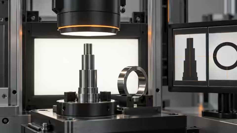
The edge used for measurement must correspond to the intended physical boundary. Compare backlight for outer silhouettes with controlled front illumination for accessible surface edges. Keep both edges and their surroundings inside the ROI. A high-contrast burr or reflection may not be the design datum.
Prerequisites and sample controls
Define the physical dimension, datum, permitted plane and unit before processing an edge. Provide a traceable reference artifact and independent dimensional answers. A visible contour or a pixel length is not a calibrated measurement. The current prepared native measurement route binds calibration and approved materials; missing approval, mismatched identity or an invalid plane must prevent a valid physical result. Hardware and production acceptance remain installation-specific.
Choose the camera route
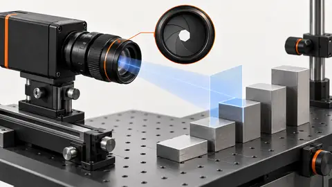
For planar edge measurements, compare a low-distortion lens with a telecentric route where height variation changes perspective. Select an area-scan sensor that resolves the edge across the full required field. Height and profile require a verified 3D route rather than a scalar pixel-to-millimeter conversion. Changing lens, focus, camera position or measurement plane requires a calibration validity review.
Run the controlled procedure
Use the same original parts when comparing light arrangements, and keep the camera, exposure and lens position fixed. Establish the region of interest in original-image coordinates and include every allowed loading position. A crop removes irrelevant background but cannot recover an invisible target. Check the full image before accepting a smaller ROI, especially when the fixture or part can move.
- Fix artifact and camera while comparing lights.
- Inspect raw edge transitions before extracting contours.
- Record edge shifts under a controlled intensity change.
- Freeze ROI and map coordinates to the approved plane.
Process map
Lighting creates the boundary evidence; ROI and the declared edge rule determine which geometry reaches calibration.
- Full image
- Light control
- ROI
- Visible target
Record the evidence
Log lighting, edge rule, fitted geometry and invalid-edge reasons. The hypothetical 501 px length is only arithmetic input; do not copy it into a measured result. Save raw pixels supporting each fitted edge.
Define the edge-selection experiment with an independently known artifact held in place. Capture the same physical boundaries under each accessible light arrangement, keeping camera pose, focus and exposure fixed. For every image, identify the intended design boundary on a separate annotation layer before looking at the fitted result. Inspect the intensity transition along the measurement direction and note additional transitions from chamfers, burrs, reflections or shadows. Compare the selected points and fitted geometry against that annotation. A candidate that consistently fits the wrong transition can have a narrow repeated spread while retaining a large physical bias. Keep the rejected boundary choice in the record so a future engineer knows why the brighter or sharper-looking edge was not used.
| Control | Required observation | Decision boundary |
|---|---|---|
| R: hypothetical plane reference | 10 mm spans 500 px; scale = 0.02 mm/px | Planning calculation, not a calibration certificate |
| D: hypothetical segment | 501 px × 0.02 mm/px = 10.02 mm | Valid only if the declared plane and calibration are valid |
| I: invalid measurement context | Missing approval, wrong plane or mismatched calibration | No valid physical value; review or refuse |
Diagnose failed cases
Saturation can flatten an edge; shadow can create a second boundary. Enlarging a fit window may add unrelated geometry. A stable wrong edge still gives repeatable but biased measurements.
Failure isolation
Compare design boundary, reflection edge and clipped fit. Only the specified observable boundary is admissible.
- Design edge
- Reflection
- Shadow
- Clipped fit
Validate independently
Change only one light variable in each trial: geometry, intensity or ambient shielding. Compare raw image contrast, saturation and the resulting mask before changing a decision threshold. Save both the successful and unsuccessful arrangements. The useful choice is the one that separates relevant classes over the allowed variation, not the one that makes a single sample look attractive.
Check known artifacts across expected light and loading variation. Retain uncertainty from edge selection; do not describe subpixel fitting as guaranteed physical accuracy.
After selecting the light, vary only one edge-processing condition in a development trial. Compare the old and proposed point sets, fit residual and reported dimension on the same original. A fit residual describes agreement with the selected image points; it does not establish traceability or total measurement uncertainty. If a proposed filter removes difficult points, retain their locations and the reason for removal rather than erasing them from the record. Test the selected rule on independent artifacts and at permitted field positions, including a boundary case that stresses visibility. Keep fitted geometry outside the declared valid calibration region invalid even when its numerical length looks plausible. The chosen ROI must preserve the specified edge surroundings and coordinate map. Freeze the light, ROI, point-selection rule and calibration applicability together, and require renewed checks after changes to the physical edge presentation.
Continue the engineering handoff
Provide the light arrangement, ROI coordinates, raw frames and masks for review. Explain whether the task requires a silhouette or a top-surface feature before selecting Deyi Vision lighting and optics. Do not silently resize a crop; any coordinate or scale conversion must be explicit in the saved workflow.
Save the original image and the resulting record together.
Sources and technical references
These references explain the methods and limits used in this tutorial. Example checks are guidance; production acceptance requires evidence from your own samples.
- Machine vision lighting basicsDeyi Vision
Illumination geometry determines whether a surface feature or silhouette is visible.
Checked - Image thresholdingOpenCV
Thresholding converts image intensity into a binary segmentation; this does not identify semantic objects.
Checked - Camera calibrationOpenCV
Camera intrinsics, lens distortion and calibration observations are required for geometric interpretation.
Checked - Geometric image transformationsOpenCV
Geometric transformations require explicit coordinate maps; resampling changes pixel interpretation.
Checked
Component and selection references
- Dimension Measurement
- Telecentric Lenses
- How to Calculate Camera Resolution for Inspection
- Stamped Part Instant Measurement
- Machine Vision Lenses
- Instant Measuring Systems
- Telecentric Lens Basics
- Telecentric Lens vs Regular Lens
- What Is a Telecentric Lens?
- Machine Vision Lens Selection Guide
- Dimensional inspection: AI workflow and calibration
- Dimensional inspection: camera and plane setup
- Dimensional inspection: diagnose bias and drift
- Validate camera calibration across the full field
- Build a vision-measurement uncertainty worksheet
- Test subpixel edge repeatability separately from bias