Problem and prerequisites
Repeated recalibration can hide a bad TCP or a wrong picking plane. Separate image localization, coordinate transformation and gripper mechanics. Use the robot’s authorized commissioning procedure for physical movements.
Prepare the test
Mark 5 independent test locations and assume a 0–2 mm part-height range. Record the active camera calibration, robot frame, TCP and pick-point definition. The example 0.20 mm limit is a proposed requirement, not achieved accuracy.
Separate the observation into image localization, coordinate transformation, robot motion and physical gripping. Preserve an image with the detected center and orientation, the transformed command, the active robot frame and tool, and the observed contact location. Without these boundaries, the same missed pick can be blamed on any layer. Use a stable reference target whose actual position can be checked independently, and perform tests within the reviewed robot operating procedure. Confirm the working plane and permitted height variation before moving the target. Record part revision and tool identity, since a changed contact feature can alter the useful pick point even when the visible contour remains similar. Do not begin by adjusting a global production offset.
Procedure
- With the robot stationary, repeat images and check whether the reported image position itself moves.
- Compare transformed coordinates against independently taught reference positions before attempting picks.
- Test permitted gripper angles while preserving the target; note whether error rotates with the tool.
- Repeat at the stated height extremes without silently changing the calibration plane.
- Change only the suspected layer and repeat all locations, preserving before/after versions.
At the five illustrative positions, first confirm that localization repeats on a stationary target without robot movement. If the image coordinates wander, investigate image quality, model selection and region configuration before changing calibration. If localization is stable, compare the transformed robot coordinates with the independently established target positions. Only after that comparison should robot approach, TCP and gripper contact be examined. Repeat a target at allowed angles while retaining the same physical center. Then test the planned height variation with the same configuration. Record each controlled change and preserve the unchanged baseline. Changing camera settings, transformation and TCP together removes the ability to tell which action corrected or concealed the fault.
Illustrative test record
Illustrative assumptions, not measured Deyi performance. Replace these values with your own signed test records.
| Record | Assumed value |
|---|---|
| Validation points | 5 |
| Part-height range | 0–2 mm |
| Calibration version | C2 |
| Proposed acceptance limit | 0.20 mm |
Run the same target first at a fixed orientation, then at several allowed angles, while preserving raw image coordinates and commanded robot coordinates. A nearly constant offset suggests checking TCP or a coordinate origin; an angle-dependent error suggests pick-point or rotation mapping. These patterns guide a test, not a diagnosis. Change one layer and repeat all five points before approving the correction; do not hide the error with one production offset.
Use patterns to select the next measurement, not to declare a cause from one miss. A constant XY difference across the field may justify checking frame origin or TCP, but another systematic source can produce a similar signature. A growing error toward the edge suggests inspecting mapping, geometry and the working plane. An error that rotates with the part suggests checking the defined pick point and orientation convention. A height-dependent shift warrants checking perspective and whether the planar mapping is being applied outside its valid plane. Keep signed residuals and actual contact observations together. A flexible or slipping gripper can produce a physical miss even when the numerical target is correct, so successful coordinate comparison is necessary but not sufficient.
Two views of the workflow
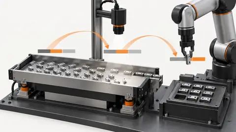
Diagnose pick offsets through frames, TCP and part height — 1
Check the image location first, then the frame transform, then TCP and gripper action. Preserve reference points at each layer.
- Image position
- Frame transform
- TCP
- Gripper
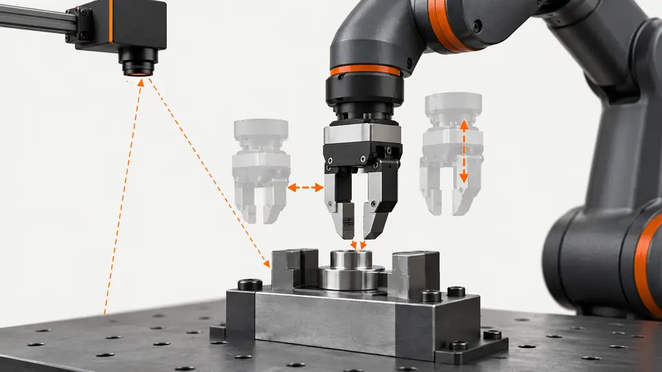
Diagnose pick offsets through frames, TCP and part height — 2
Error patterns direct investigation but are not diagnoses. Verify the suspected change against independent targets.
- Constant shift
- Angle dependence
- Height dependence
Troubleshooting
- A constant error suggests an origin or TCP check, but does not prove the cause.
- Angle-dependent error suggests a tool-center or pick-point problem.
- Height-dependent error requires checking perspective and the transform’s plane assumptions.
Acceptance and handover
Close the fault only when signed errors and real pick results meet the agreed limits at all tested angles and heights. Document which layer changed; a smaller calibration residual alone does not prove correction.
Set acceptance limits before testing and retain the original evidence. The examples here do not establish a supplied model’s capabilities.
Approve a correction only after repeating the full validation set with new presentations, not just the original failing point. Check the intended tool and production approach, and verify that the active frame and calibration revisions match the recorded correction. Demonstrate restoration of the previous accepted configuration if the candidate change fails. When the permitted height range requires a different sensing or calibration method, document that scope instead of claiming a planar offset fixes it. Handover includes a layer-by-layer evidence table, baseline and corrected settings, independent target positions and actual pick outcomes. The proposed 0.20 mm value is an example limit requiring application approval, and the 0–2 mm height exercise describes a controlled test rather than a guaranteed operating range.
Sources and technical references
These references explain the methods and limits used in this tutorial. Example checks are guidance; production acceptance requires evidence from your own samples.
- Hand-eye calibration wizard — EYE+ 5.4Asyril
Paired vision/robot positions, production plate, coordinate units and manual pick validation.
Checked - Knowledge database — EYE+ 5.4Asyril
Official knowledge topics on vision calibration, recipe portability and hand-eye good practices.
Checked
Component and selection references
- Robot Guidance
- Robot Guidance Pick and Place Positioning
- Flexible Feeder Robot Loading for Small Parts
- Flexible Feeders & Workstations
- Flexible Feeding & Robot Loading
- Flexible Feeder Selection Guide
- Tune a flexible-feeder recipe with controlled trials
- Validate hand-eye calibration across the tray
- Part positioning: acceptance and motion handoff
- Part positioning: an AI-assisted pixel workflow
- Part positioning: camera and coordinate setup
- Part positioning: lighting and ROI stability
- Part positioning: locate the cause of pick offset
- 2D vs 3D Machine Vision
- 3D Vision Cameras