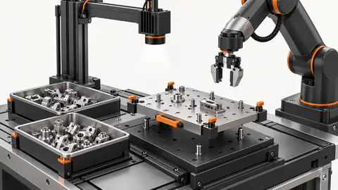
Problem and prerequisites
Nominal camera rate and robot speed cannot predict station throughput. Measure the period between consecutive completed picks and the stages that block the next pick. Use the real gripper and representative load.
Prepare the test
The sequential example assumes 500 ms vibration, 200 ms settling, 80 ms capture/analysis and 400 ms pick: 1180 ms per cycle, about 50.8 cycles/min. It excludes replenishment, failures and downtime and is not demonstrated production output.
Define the measured cycle boundary in the control sequence, not from a promotional throughput number. For a feeder cell, vibration start to the next permitted vibration start is one useful boundary, but the production objective is successful delivery of parts. Record the intended loading envelope, robot path, tooling and inspection requirement before optimizing. Confirm when the tray must be stationary and when the robot may enter the pick area. Use the approved sequence and collision assessment for any overlap proposal. A faster camera does not improve a cycle dominated by waiting or robot motion unless that stage is actually on the limiting path. Keep settings and timestamps together so that comparisons refer to the same cell configuration.
Procedure
- Timestamp vibration start/end, exposure, coordinates ready, robot request and pick completion.
- Keep one cycle identifier through every device; separate waiting from active processing.
- Measure repeated cycles at low, nominal and high tray population.
- Identify which stages can actually overlap without vibrating during exposure or disturbing a pick.
- Change the largest controllable delay and repeat under identical conditions; include failed picks and replenishment.
Instrument start and completion of vibration, settling, image acquisition, detection, robot request, pick and transfer. Where the controller exposes separate acknowledgements, log those as well. Use a common monotonic clock for host events; if controller and vision timestamps use different clocks, establish their relationship or measure external signals. Do not calculate cross-device intervals from unaligned clocks. Observe whether the cell is waiting for a condition, a communication acknowledgement or a configured fixed delay. Capture the reason for a no-candidate cycle and for a failed pick. Repeat with representative loading rather than timing only the first favorable pick after replenishment. A screen’s displayed processing time may omit acquisition, communication and queue delay.
Illustrative test record
Illustrative assumptions, not measured Deyi performance. Replace these values with your own signed test records.
| Record | Assumed value |
|---|---|
| Vibration interval | 500 ms |
| Settling interval | 200 ms |
| Capture and analysis interval | 80 ms |
| Pick interval | 400 ms |
Measure the interval from vibration start to the next permitted vibration start, and retain each stage timestamp. The illustrative sum is 1180 ms only if all four stages are sequential. Do not subtract overlapping time unless the measured control sequence and collision review permit that overlap. Report successful transferred parts divided by elapsed production time separately from theoretical cycles. Include failed picks, refilling and recovery in the production measurement.
Draw a timeline using the measured stage boundaries and identify the stage that prevents the next cycle from starting. For sequential operation, the example’s four intervals add to 1180 ms. If allowed stages overlap, calculate the elapsed interval from the actual timeline rather than summing all durations or subtracting a guessed overlap. Compare the result against controller event traces. Report the distribution and worst observed cycle for the tested conditions, not only a selected minimum. Keep the theoretical inverse-cycle calculation separate from delivered-part rate. Failed attempts, candidate scarcity, replenishment and recovery can lower delivered output even when the nominal timeline remains fast. Explain which losses are included in each reported number.
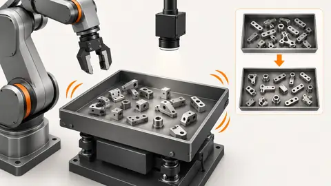
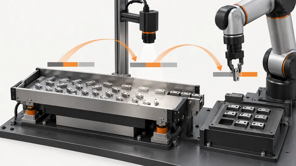
Two views of the workflow
Measure the feeder, camera and robot cycle as one system — 1
The sequential path makes the sum visible; measured timestamps determine whether overlap is permissible.
- Vibrate
- Settle
- Capture
- Pick
Measure the feeder, camera and robot cycle as one system — 2
Active work, waiting and overlapping work need separate interpretation. Report completed parts rather than image rate.
- Active stage
- Waiting
- Permitted overlap
Troubleshooting
- A high average rate can conceal long tail cycles; inspect the slow events.
- Double-counted overlapping stages exaggerate cycle time; use timestamps rather than adding catalog numbers.
- Reducing settling that creates false candidates is not a valid improvement.
Acceptance and handover
Accept the required completed-pick rate together with failure and waiting limits over the agreed run. Preserve timing evidence and load range. The 50.8/min calculation is an upper illustration for a sequential assumed cycle, not a supplier guarantee.
Set acceptance limits before testing and retain the original evidence. The examples here do not establish a supplied model’s capabilities.
Validate a proposed timing change with the complete operating sequence and new representative loads. Shortening settling requires evidence that detection and actual gripping still succeed; shortening a communication wait requires proof that the receiving controller has reached the intended state. Do not remove a necessary interlock merely because its time appears in a chart. Repeat the original configuration as a control and retain both timelines. Handover should identify cycle boundaries, clock method, permitted overlaps, excluded downtime and actual delivered-part records. Agree the production acceptance criterion before testing, including handling of failed picks and refill periods. The illustrative 50.8 cycles/min calculation is a theoretical rate for the stated sequential assumptions and is not a measured Deyi cell capacity.
Sources and technical references
These references explain the methods and limits used in this tutorial. Example checks are guidance; production acceptance requires evidence from your own samples.
- Create new multi-feeding recipes — EYE+ 5.4Asyril
Recipe stages include candidate selection, pick point, angle, gripper conditions and vibration configuration.
Checked - Asyril AcademyAsyril
Official training covers camera setup, recipes, hand-eye calibration, communication and integration.
Checked
Component and selection references
- Flexible Feeder Robot Loading for Small Parts
- Flexible Feeding & Robot Loading
- Flexible Feeders & Workstations
- Flexible Feeder Selection Guide
- Robot Guidance Pick and Place Positioning
- Validate hand-eye calibration across the tray
- Part positioning: acceptance and motion handoff
- Part positioning: an AI-assisted pixel workflow
- Part positioning: camera and coordinate setup
- Part positioning: lighting and ROI stability
- Part positioning: locate the cause of pick offset
- Diagnose pick offsets through frames, TCP and part height