What the test resolves
A low calibration fit residual does not establish dimensional accuracy across the field. Test independent reference distances at production positions and heights.
This is a vendor-neutral commissioning method. Check the exact camera, lens, sensor or controller manual before changing settings. The numerical worksheet is hypothetical, not a Deyi Vision measurement or a product specification.
Operating prerequisites
Use a dimensionally characterized target that was not used to tune the final model. Calibration remains tied to lens, focus, ROI, resolution and measurement plane.
Separate the observations used to fit calibration from the observations used to validate it. A low fitting residual may reflect a model that fits its own training points without representing the production field. Define the measured quantities, part plane and permitted height range first. A planar calibration should not silently be applied outside its justified plane, and an uncharacterized printed target is unsuitable as the sole accuracy reference.
Bench and records
Prepare a grid or length artifact, height stage and raw-image archive. Save calibration file, units, coordinate convention, fitting residual and reference uncertainty.
Use an independently characterized artifact and record its reference values, uncertainty, orientation and support condition. Establish the field grid and height fixture, keeping the calibration version, image ROI, lens settings and coordinate units fixed. Prepare a result row for location, height, measurement direction, reference value, measured value and signed error. Save raw images so a later review can distinguish feature extraction mistakes from the coordinate transformation itself.
Run the test
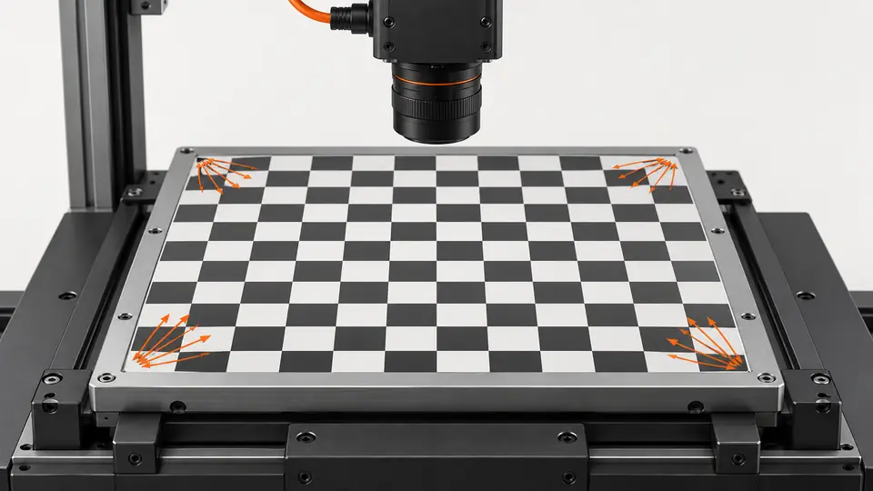
- Freeze the calibration and place the independent target on a 5 × 5 field grid.
- Measure horizontal and vertical lengths at nominal height; include all corners.
- Repeat at minimum and maximum permissible height without refitting.
- Plot signed error by location and retain maximum absolute error separately from RMS.
Fit and freeze the proposed model using its intended calibration data, then keep the independent artifact out of all subsequent fitting. Measure the planned field positions and heights in both required directions. Return to a reference position during the run to check stability. If a validation failure leads to a model change, create a new version and rerun independent validation; do not replace only the failed rows in the old result table.
Hypothetical worksheet
Hypothetical validation errors are +0.004 mm centrally, +0.012 mm at one corner and +0.030 mm at another. A declared 0.020 mm maximum-error rule fails the last point even if average residual is small.
error_i = measured_i - independent_reference_i
RMS = sqrt(sum(error_i^2) / N)
Example errors: center +0.004 mm; left corner +0.012 mm; right corner +0.030 mm
example acceptance: max(abs(error_i)) <= 0.020 mm| Quantity | Hypothetical value | Meaning |
|---|---|---|
| Center error | +0.004 mm | Hypothetical independent validation |
| First corner error | +0.012 mm | Within example 0.020 mm limit |
| Second corner error | +0.030 mm | Fails example 0.020 mm limit |
The example compares signed physical errors with a declared maximum permitted error. Preserve error sign because a spatial pattern can reveal scale or distortion effects. Report the worst required location alongside any overall summary. Reprojection error is expressed in image coordinates under the calibration model, whereas an independent dimension error concerns the reported physical quantity. Neither can be substituted for the other merely because both are described as calibration residuals.
Test sequence
Test sequence
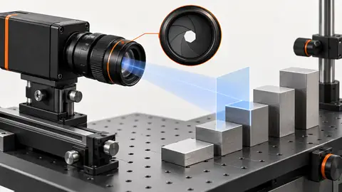
Cross the field grid with required object heights to reveal errors hidden by center-only tests.
- Center
- Edges
- Corners
- Height range
Interpret the evidence
Interpret the evidence
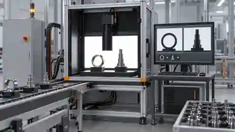
Freeze the fitted model before independent measurements and error mapping.
- Fit model
- Freeze
- Independent target
- Error map
Place each independent result on the field diagram and identify its height and direction. Mark untested cells explicitly. Patterns confined to corners can suggest an inadequate model or optical performance, while changes with height can reveal the limitations of a plane-based mapping. Keep these as diagnostic hypotheses until verified; the diagram identifies where additional evidence is needed rather than automatically choosing a distortion model or correction.
Troubleshooting
- Radial growth suggests distortion-model or field coverage problems.
- Height-dependent error can be perspective/magnification change; a planar model cannot silently compensate arbitrary depth.
If every location has a similar scale error, check reference units, image resizing and pixel-to-world conventions. If directions disagree, check target orientation and measurement geometry. If only a subset of points changes between runs, inspect extraction and fixture stability. A good average with a failed critical corner remains a failed application requirement. Do not remove inconvenient validation points unless there is recorded evidence that the observation itself was invalid.
Acceptance and handoff
Require every field/height and length orientation to pass its agreed error budget, including reference uncertainty. Keep fit and independent-validation results distinct; invalidate calibration after relevant optical or ROI changes.
Archive the raw files, settings, sample identifiers and decision limits together. Discuss the documented requirements with Deyi Vision using the related product and preparation guides below.
Approve the frozen model only after fresh independent measurements meet the declared limits throughout the required field and height envelope. Include the reference uncertainty and repeatability when interpreting closeness to the limit. Archive the artifact identity, full signed-error matrix, raw captures and calibration version. Changes to lens, working distance, ROI, image scaling or measurement plane require checking whether the validation remains applicable and repeating the affected tests before release.
Sources and technical references
These references explain the methods and limits used in this tutorial. Example checks are guidance; production acceptance requires evidence from your own samples.
- Camera CalibrationOpenCV
Calibration projects object points into images and evaluates reprojection residuals.
Checked - Gauging Depth of Field in Your Imaging SystemEdmund Optics
Depth of field should include a resolution criterion; sharpness alone does not guarantee magnification stability.
Checked
Component and selection references
- Telecentric Lens vs Regular Lens
- Machine Vision Working Distance Guide
- Instant Measuring Systems
- Dimension Measurement
- Telecentric Lenses
- Machine Vision Lenses
- Telecentric Lens Basics
- What Is a Telecentric Lens?
- Machine Vision Lens Selection Guide
- Stamped Part Instant Measurement
- Dimensional inspection: AI workflow and calibration
- Dimensional inspection: camera and plane setup
- Dimensional inspection: lighting and edge ROI
- Dimensional inspection: diagnose bias and drift
- Build a vision-measurement uncertainty worksheet
- Test subpixel edge repeatability separately from bias