Purpose and operating boundary
Find whether a disappearing gap comes from real capture evidence, coordinate drift or processing that merely paints over the defect in a derived mask.
This tutorial defines an engineering evaluation, not a ready-to-run product certification. The current Deyi Vision public PC example covers an EAN-13 workflow on confirmed sample images. Native OCR and detection work in the engineering code must be checked against the installed runtime, bound models and job before use. A browser template does not prove browser execution: the planned OpenCV.js backend needs separate verification. Cloud recognition requires explicit approval of the image scope, provider, model and cost. A review archive is not an executable release package. Camera, firmware and driver compatibility require their own check. All worksheet values below are hypothetical; they are not Deyi Vision measurements or customer results.
Prepare the evidence
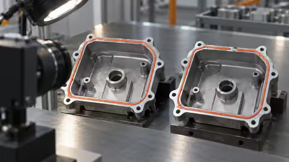
Freeze a visible-gap original and a continuous control, plus the exact transform and preprocessing revision. Keep the physical appearance answer unchanged. Define the visible acceptance feature before building a seal or bead mask. A tamper-seal edge, a heat-seal band and an adhesive bead have different physical meanings and must not share an undeclared appearance rule. Record the reference path, permitted projection, substrate and state of the material at capture. Wet adhesive, cured material and a reflective backing can produce different boundaries without an equivalent change in joint integrity. Include a deliberately visible gap, an offset path, a plausible reflection and an obscured section as separate controls. The assigned image rule evaluates observable surface appearance only. It cannot establish airtightness, leak rate, peel strength, bond strength, cure or a hidden interface. Those claims need their own process-specific evidence. If the required interface is hidden, return insufficient evidence or choose another validated observation method; do not complete the path from an expected drawing. Troubleshoot from the earliest observable divergence. Replay the same saved source through the unchanged baseline and candidate and compare intermediate images, regions, numeric values and result states. If the source itself differs, the comparison no longer isolates the algorithm. Change a single suspected cause, write the expected effect before running, and retain the negative result when the hypothesis fails. Separate unreadable evidence, a rule mismatch, missing dependencies and an execution fault; they require different remedies. A replay can reproduce a software failure but cannot validate the live trigger, illumination timing or physical reject path. Keep those acquisition and line checks as separate follow-up experiments. Write a failure record that another engineer can replay without guessing which image or revision was used. Include the original source, affected region, actual output, expected disposition and the first divergent intermediate result. Record whether the symptom appears on replay, live capture or both. After a correction, rerun the original failure and the previously successful neighboring conditions. A fix that removes one alarm by excluding its region or accepting a missing result changes the requirement rather than resolving the cause. If the failure remains unresolved, keep the affected operation in Review or inhibited state with its reason; do not label an untested workaround as a validated solution.
Procedure
- Replay the failed source before altering settings and inspect the full path with its original coordinates.
- Compare masks before and after morphology, recording which original pixels support the newly connected section.
- Change only the suspected optical or processing cause; capture a new material event rather than overwriting the old failure.
- Replay good, gap, offset and hidden controls to verify that the fix preserves true missing sections and review boundaries.
Interpret the trial
In the hypothetical diagnostic record the raw gap spans 6 px. A candidate mask reports 0 px after a closing operation, while the unchanged source still shows 6 px. That is not evidence that the joint healed; it demonstrates an image-processing discrepancy requiring rejection or further investigation. No kernel size or global correction rule is prescribed here.
Recording worksheet
| Record | Value | Interpretation |
|---|---|---|
| Original gap | 6 px | Visible source evidence retained |
| Candidate mask gap | 0 px | Not physical repair; compare the original 6 px |
Two engineering views
Two engineering views · 1
The diagram shows the order of checks. Each arrow requires recorded evidence; it does not imply an implemented automatic connection. Failure image → First divergence → Hypothesis → Replay.
- Failure image
- First divergence
- Hypothesis
- Replay
Two engineering views · 2
The diagram shows the order of checks. Each arrow requires recorded evidence; it does not imply an implemented automatic connection. Original failure → Correction → Neighboring cases → Retained evidence.
- Original failure
- Correction
- Neighboring cases
- Retained evidence
Failure diagnosis
- A reflection following the light angle is not independent evidence of adhesive continuity.
- A crop shift can move the inspected path off the gap; compare overlays on the same original before accepting a better result.
Acceptance and handover
Close diagnosis only when the expected intermediate evidence improves for the stated cause on new independent controls. Preserve the original failure, rejected candidate and unresolved hidden regions; a visually repaired mask cannot certify leak or bond strength.
Keep the source images, the expected decision, the exact revision and the complete result record together. Freeze the evaluation set before selecting the final parameters. If those answers are later used to tune the workflow, mark that set as development data and obtain a new independent acceptance set. Keep Review, NoResult, execution error and missing acquisition visible in the denominator; do not turn them into passes by filtering rows. Save a reproducible failure alongside the successful sample. The handover should identify who may change the recipe, how a prior approved revision is restored and which device output remains inhibited until acceptance. A software result alone does not establish that a moving physical part reached the correct destination.
Sources and technical references
These references explain the methods and limits used in this tutorial. Example checks are guidance; production acceptance requires evidence from your own samples.
- Deyi Vision Vision WorkbenchDeyi Vision
The public PC example is bounded EAN-13 saved-image scope; templates are not universal executable support or production acceptance.
Checked - Pharmaceutical Packaging Code Label and Seal InspectionDeyi Vision
Define observable seal presence, material/lighting variation and traceable reject handling with real samples; not proof of leak or strength.
Checked - Morphological TransformationsOpenCV
Opening/closing alter foreground geometry and can suppress gaps; before/after masks need independent controls.
Checked - Camera CalibrationOpenCV
Camera calibration and distortion correction have declared geometry; a nominal pixel scale does not validate 3D or functional integrity.
Checked
Component and selection references
- machine vision software
- Pharmaceutical Packaging Code Label Seal Inspection
- Automated Visual Inspection
- Machine Vision Systems
- Battery Tab Weld Height Inspection
- Balluff Vision Sensor Alternative
- Datalogic Barcode Reader Alternative
- Banner Vision Sensor Alternative
- Choose lighting and ROI for visible assembly checks
- Troubleshoot visible assembly verification failures
- EAN-13 traceability: duplicates and missing reads
- Camera setup for visible fill-level inspection
- Lighting and ROI for a visible liquid boundary
- Troubleshoot unstable visible fill-level decisions
- Check laser-profile datum and missing-data behavior
- OCR labels: unreadable versus wrong text
- Set up a camera for open-package completeness checks
- Choose lighting and ROI for open-package contents
- Troubleshoot false package-completeness decisions
- SKU color sorting: channel and drift diagnosis
- Surface defects: false-alarm diagnosis