Problem and prerequisites
Correct decoding does not guarantee rejection of the correct part. Use an independent part identifier, a measured transport path and feedback at the reject station. Encoder support and industrial interfaces must be confirmed for the selected equipment.
Prepare the test
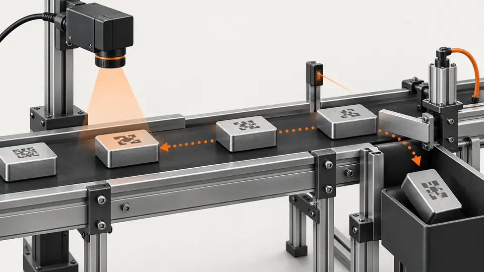
Assume 800 mm between imaging and reject, 400 mm/s constant speed and 100 ms actuator response. Travel takes 2 s; the illustrative decision allowance is 1.9 s before extra reserve. These are design assumptions, not timing specifications.
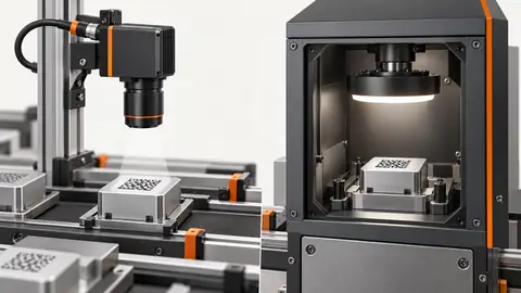
Survey the complete path from part detection to the physical reject point before calculating a delay. Record where position is established, where the image is taken, where the decision becomes available and where the actuator contacts the part. Measure the effective travel distance along the conveyor, not a diagonal drawing distance. Confirm the permitted speed range, minimum part spacing and whether parts can slip relative to the conveyor. Choose timed tracking only when its assumptions can be maintained and tested. Encoder position tracking also has assumptions: the encoder measures a defined motion, its counts have known units and the part remains associated with that motion. Neither method automatically identifies a slipping part.
Procedure
- Create the part event at the entry sensor and attach the capture result to that identifier.
- Measure encoder distance to the reject position; define handling of gaps and closely spaced parts.
- Queue each decision with its target position, preserving identity through speed changes.
- Command rejection early enough for the measured actuator response, then record reject confirmation.
- Test unreadable codes, delayed results, stops and restart; an expired result must not attach to the next part.
Create a queue entry at the part trigger with identity and initial position, then attach the reading result to that same entry. Exercise alternating good and reject samples at the intended spacing to reveal an off-by-one association. Observe the decision arrival, scheduled reject command, actuator operation and reject confirmation as separate events. A pass decision arriving after the action deadline must not cancel a reject already assigned to a different part. Record actual output timing using suitable instrumentation or controller traces, rather than estimating it from the screen refresh. Repeat at the allowed speed extremes and during permitted acceleration or deceleration. Keep simultaneous parts in the queue; one shared delay variable is insufficient for several in-flight parts.
Illustrative test record
Illustrative assumptions, not measured Deyi performance. Replace these values with your own signed test records.
| Record | Assumed value |
|---|---|
| Travel distance | 800 mm |
| Conveyor speed | 400 mm/s |
| Decision deadline | 1.9 s |
| Trigger identifier | T200 |
The 1.9 s command time assumes constant speed and a measured 100 ms actuator delay. If speed drops from 400 to 320 mm/s, the same 800 mm travel takes 2.5 s, so the old timer acts 0.5 s too early. With encoder tracking, bind the decision to a part position and verify position-count units and reset behavior. When tracking is lost, apply an agreed containment action; never send an unassigned reject pulse.
The distance/speed calculation establishes nominal travel time, not a complete output budget. Subtract measured actuation delay and the agreed margin from the arrival time to obtain the command deadline, and compare that deadline with the latest available inspection decision. Transfer, processing and queue delay all consume that budget. If the reader result misses the deadline, apply the defined late-result disposition to the affected identity. For encoder control, express the target in the verified count units and record the trigger count, target count and actual output count. Handle conveyor reset and counter wrap according to the controller design. Do not preserve old target counts across a restart without a validated position-recovery method.
Two views of the workflow
Track barcode results to the correct conveyor reject — 1
One part identifier links acquisition, position tracking, decision and confirmed removal.
- Entry sensor
- Capture
- Position queue
- Reject feedback
Track barcode results to the correct conveyor reject — 2
Constant-speed time estimates are planning checks. Changing speed requires position evidence and independently managed result expiry.
- Time estimate
- Position tracking
- Expired result
Troubleshooting
- A time-only delay drifts when conveyor speed changes; use verified position tracking where required.
- Missing reject feedback must raise a station fault instead of recording successful removal.
- A late result must follow the agreed hold or reject policy, never replace the next queued result.
Acceptance and handover
Verify identity at both camera and reject for every trial. Repeat at minimum and maximum speed and after a stop; record position error and response reserve. Calculate production limits from measured timing, not the 1.9 s illustration.
Set acceptance limits before testing and retain the original evidence. The examples here do not establish a supplied model’s capabilities.
Acceptance requires evidence of the physical destination, not merely a successful software output call. Compare every test part’s expected decision with its observed reject or pass path and any reject sensor feedback. Introduce a missing result, a delayed result, a lost encoder signal and a restart using the agreed controlled test procedure. Verify that the affected parts are contained and that later parts are not assigned stale decisions. Define what to do when the reject sensor is unavailable or contradicts the command; a command acknowledgement alone does not prove removal. Hand over distances, measured actuator delay, tracking rules, fault dispositions and trace records. The hypothetical timing values are a worksheet example and cannot be copied into production settings without site measurements.
Sources and technical references
These references explain the methods and limits used in this tutorial. Example checks are guidance; production acceptance requires evidence from your own samples.
- DataMan 360 Reference ManualCognex
Product-specific acquisition, trigger modes, image filtering and multi-code behavior; used as a principle reference, not a Deyi specification.
Checked - Acquisition Timing InformationBasler
Distinguishes acquisition stages and model-specific timing limits.
Checked
Component and selection references
- Barcode Reader for Manufacturing Lines
- Packaging Label and Barcode Inspection System
- Barcode & Traceability
- Industrial Barcode Readers
- Industrial Barcode Reader Selection Guide
- What Is DPM Barcode Reading?
- DPM Code Reading on Reflective Metal Parts
- Packaging Label and Barcode Traceability
- Direct Part Mark Code Reading on Metal Parts
- Cognex DataMan Alternative
- Datalogic Barcode Reader Alternative
- Omron Microscan Barcode Alternative
- Zebra Fixed Scanner Alternative
- Logistics Barcode Sorting
- Printing and Label Inspection
- EAN-13 traceability: line acceptance
- EAN-13 traceability: decode and data rules
- EAN-13 traceability: camera sampling
- EAN-13 traceability: lighting and quiet zones
- EAN-13 traceability: duplicates and missing reads
- Multiple codes: region rules and duplicate-read control
- Check OCR text against barcode and batch data